
The addition of a flash system into the camera design wasn't something I'd thought of during the sketching/planning stage. As a keen amateur fashion photographer, i'm a firm believer that on camera flashes are the most utterly horrible things which cast hard light over your image. Hard light is a result of one thing, light coming from a small space. It creates crisp hard shadows and lots of contrast. This isn't always a good effect, and is especially unflattering to portraits of people. Light from a large area, such as a window, casts much softer light which is kinder to the skin, helping skip over blemishes. However, when designing a camera, there just isn't the option of building in a flash like this.

Rather than leave the flash out however, it occured to me that I had a fair amount of dead space around the lens. Thanks to the short back focal length of the lens unit, the optics become only about half the diameter of the front lens surround. That leaves a big gap between the outer edge of the optics and in the inner edge of the aluminium lens surround; a perfect location to deploy a ring flash!
A ring flash is slightly different to a normal flash. It is positioned around the end of the lens, and throws light evenly at the subject. Compared to a normal flash which is often located off at an angle away from the lens, the light is cast in a much nicer manner, and causes much less hard contrasty shadows (see above). This is why ring flashes are used in many professional applications, from beauty shots to macro and forensic photography where ugly shadows would hide essential detail.

With about a 3mm ring of space to play with, I went to RS Components in search of white daylight rated board mounted LEDs. The daylight rating refers to the colour temperature of the light cast by the LED. 5700k is roughly similar to overcast daylight, a good medium to use for natural looking photographs. It is important to avoid LEDs with colour temperatures at a lower value such as 4000k, as they will give the images a warmer redish tint.


With limited space, I didn't have many potential components to choose from. I ended up picking the LED shown above due to it's remarkably small package size. At 3.1 by 1.5 there is plenty of room to mount it onto the board without it's corners running into the ring shaped circuits inside and outside diameters.
The downside to using such small LEDs is the low luminosity power output. This can't really be helped. To attempt to compensate, a ring array of 16 is built onto the circuit, helping to evenly spread the light around the frosted acrylic output ring mounted infront.
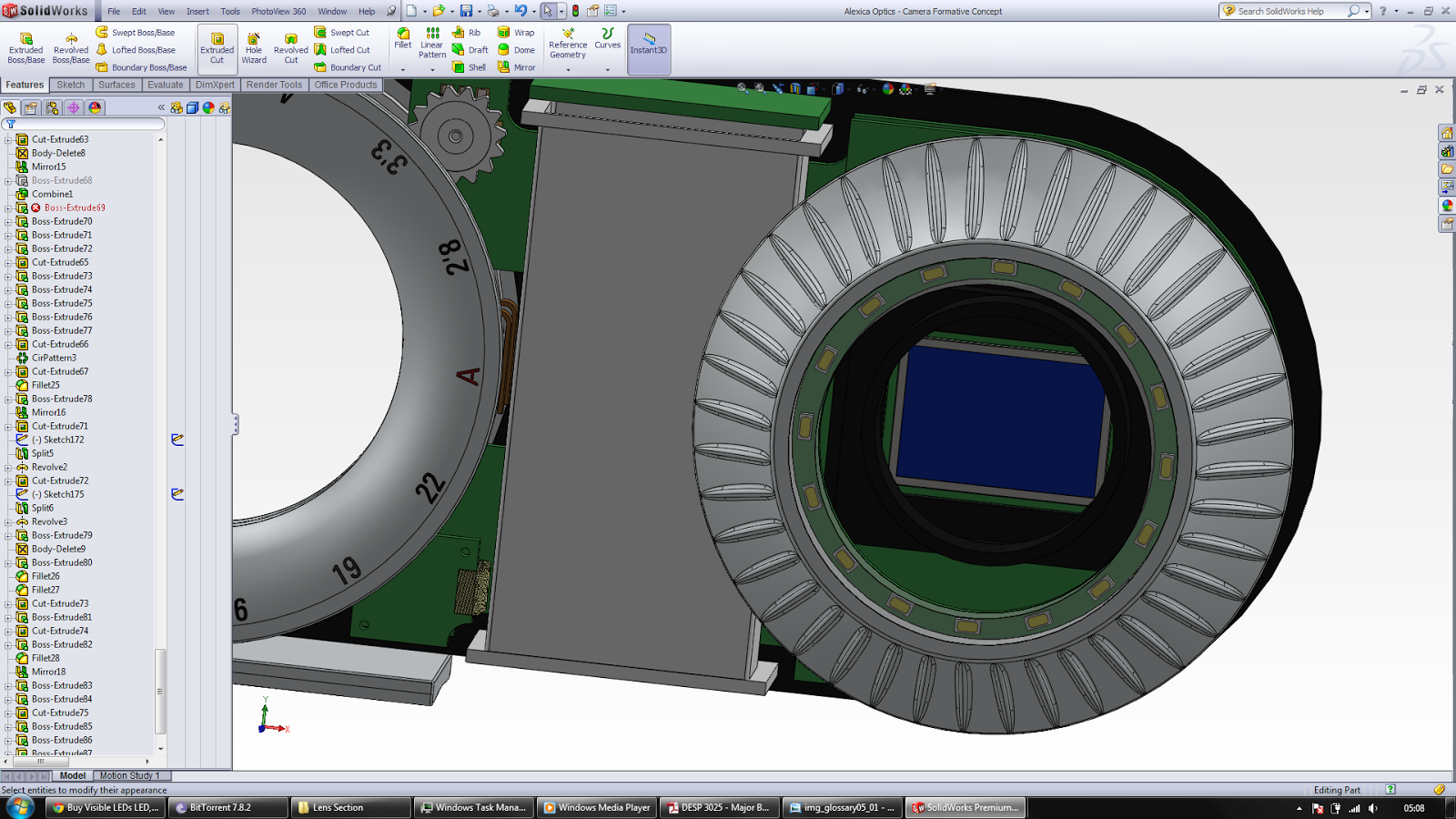
Here is the final ring flash assembly. It will be wired directly to the circuit board underneath and fed by a capacitor. Although low powered, the choice of LED does mean there shouldn't be too much strain placed on the battery.
