

Day 2 started straight off from where I stopped the evening before. I had one optic half cut, so it was time to take that part and cut the reverse side. The evening before I had tried to cut the reverse side only to have the part ripper out of the custom made collet over and over again. The collet is designed to hold a 50mm diameter optic on only a 1mm wide ring around the entire outside edge. 1mm obviously wasn't enough for it, so I put the alli collet back into the manual lathe and disengaged the gear box, spinning the chuck by hand and using the boring tool to take an extra half milli out of the collet, increasing the width of the holding area to 1.5mm.


In the end it the optic jammed into my altered collet and held well in the cnc machine, which was a relief because the back side cut was fairly deep and I was worried the tool was going to just rip the part out again. It cut fine however and within a few minutes I had a completed optic.


Ensuring the correct width was down to measuring using digi callipers and altering the cnc programs billet offset. In the end I was able to get very close to the thickness I needed. I can't remember what number I was after exactly, but I think it was 2.09mm, so i'd say the thickness is within tolerance.
Something about this part worrys me however. This is Optic A of the 50.2'8. Surface 1 is facing the front of the assembly and Surface 2 is facing the back (they're numbered top down from air side down to sensor side). Surface 2 has such a shallow radii that I'm scared it's going to be worn away in the polishing process. Now really, this shouldn't be a worry. I know the machine cut the face correctly, I can see that the surface curvature changes, and I know that buffing wheels and P1000/6000/12000 won't alter the radii (not enough to be a problem anyway ((lets ignore cumulative errors for now)) ). So why the worry? Well it just doesn't look right... I don't like it when it doesn't look right. The surface must push out about 1mm, not a lot. If I had been sensible in the design process, I would have edited any radii above a certain value up to infinity and re-optimised to avoid potential finishing problems like I am worried about here. I'll know for next time. We'll see whether this causes me a problem when the lens is finished.


I am making two identical optics at a time so that I can manufacture two full 50mm 2.8 lenses at the same time. I had a small bit of PMMA left from an existing end of billet, so I jammed it in the collet and set to work on that. The cutting profile was running too close to the chuck for the softwares liking, so it whined and refused to run. I ended up spacing the collet off the chuck teeth using bits of space 3mm plastic sheet (the red things in the images below) This gave just enough extra billet length for the program not to moan.


With that done, it was onto trying to solve the problem of the week. The CNC machine didn't read the concave DXF files i'd given it. That's a majorrrrrrrr problem. But more of a problem than that is the tool (boring bar) that would cut the profile (if it could be read) wasn't even loaded into the machine. It had been taken out of the tool post during a previous job. So the next thing to do was put it back in it's place and re-calibrate it in the control software.


Okay so let's explain a few things. The CNC machine uses a rotating automatic tool turret to select which tool to use. There are 8 tool positions, allowing for 8 tools to be loaded into the machine and used. The tool turret is a circular hunk of steel which holds the tools in place, and it can rotate so that any of the 8 tools can be moved into the cutting position. Here's where there's a problem. Below is a photo I took where I manually jogged the servos so that the turret was close to the chuck (around about where the tools would usually start cutting). Who can see the problem??? The hole at the bottom of the turret is where the boring bar should be. Pretty good job it's not there.... I understand why it was taken out now, if the machine was running the tool would collide with the chuck and completely mangle it's self, not good news....


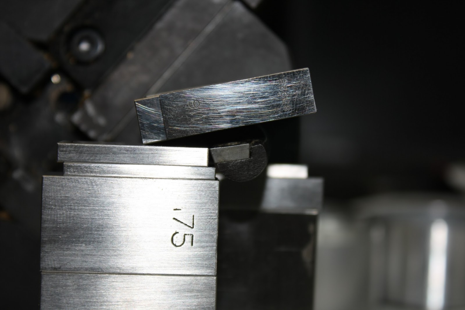

Me and Garry used a stacks of slip gauges to set to the tool to exactly where it should be, with the cutting tip at the correct angle of rotation and the correct length away from the face of the turret. Slow work, but worth it to get the tool back in action. The tool now rested in a different tool post to what the software thought, so i took a note of it's index position (the numbers in circles shown below) and swapped it on the control software.

Having got the boring bar in place I decided to test it out by cutting a part I needed which involved a boring a ledge. The part is a 25mm collet designed to hold a 25mm diameter optic on a 1mm edge thickness. The machine cut it just fine and after taking it out I cut lines down the barrel and removed any burrs that might scratch the optic.


Having cut a couple of acrylic optics now, I was used to how the acrylic cut. Every material has a feel and the acrylic was nice and easy and hadn't caused me any problems thus far. This was about to change! I cut the double convex optic and the result is shown below. It looks like a frostie! Something tells me the image quality isn't going to cut it hahaa. Basically the machine was cutting it all fine up until the final long pass across the entire surface. On this pass, all the swarf just melted itself back onto the surface, making what can only be described as an absolute mess.

In the end the problem turned out to be in how the contorl software was converting my DXF profiles into machine instructions. The machine was configured to have two tool feed speeds for cutting, one roughing and one final quality. The final quality feed speed was half the speed of the roughing feed, so as the tool was cutting, more heat was building up and the swarf was just liquefying and then re-solidifying on the other side of the tool. I went into the code and manually bumped the final cut feed speed up to the same as the roughing speed, and ended up with a good final surface quality, as seen below.

With the convex side cut i simply parted off on a manual lathe. I polished and buffed the surfaces with the piece in the collet as the smaller diameter means that the optic is difficult to hold against the wheel without support.


Here are the finished results. I labelled an envelope and kept them safe ready for assembly. The surfaces weren't perfect at this point, but I planned on re-polishing everything before final assembly anyway.
