Although I have the aluminium housings already made, there is still the issue of how to hold the optics within the barrel, and how the STOP will be switched out. The optical design I have come up with requires the STOP to be placed dead centre between the front two elements. The sketch above is the design which I came up with off the top of my head.
The first step in transforming my 2D optical design and barrel sketch (both cross sections) into 3D forms is to take a STL export from ZeMAX. This file contains a three dimensional version of the entire optical system. This can be imported into SolidWorks and converted into a usable solid model CAD file. This is what can be seen above, with a cross section taken away to reveal the same cross section as I was staring at for so long in ZeMAX.
One of the most essential parts of the design is the size of the air spaces between the elements. This is as much of an important part of the system as the actual elements, because they can affect the image quality drastically if the wrong size. I decided to use a dependable material, aluminium, to create rings which will hold the optics are the correct positions. The system is split with the front element separate from the rear two, in order to allow the STOP to be placed between them. Therefore there are two aluminium rings shown above. The rear ring holds both the rear elements, which will have their edges pushed up flush against the rings edges to ensure they are the correct distance apart (assuming the ring is cut absolutely accurately).
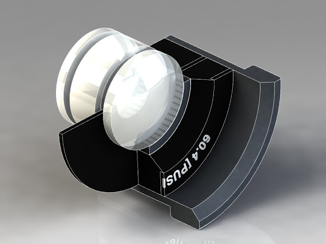
To hold the rings in place, a holding material is required to interface between them and the barrel of the lens. For this I am using nylon. Again, it is turned into two rings allowing a gap for the STOP disc to be placed in between. I have also included a step at the front (left hand side) to give the opportunity to include a laser etched name plate.
The name plate is shown in the in the screen shot above. The text loops are generated by the software and will allow for hatching to be applied later on in accordance to the laser cutters requirements. The text is the name of the lens, alexica. 60.4 [PUSH.2'8] AC-PC (3) {0}.
Here I have added the pre-manufactured aluminium barrel into the assembly to complete the housing design.
Here you can see a 3/4 cut through the body revealing how the optical system is held in place. The black disk is the STOP, which can be dropped in by removing the rear half of the lens (optics, alli ring, nylon ring which are all joined together). A STOP disc must be in place for the lens to work, as it's thickness contributes to the spacing between the front and rear elements.
Finally here is a whitewash render to show clearly how my sketch has translated into a 3D form. With plenty of time spend on lathes, I am confident that this design will be fast and easy to manufacture manually.


