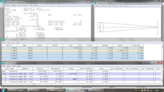
The majority of lens design isn't manually crunching numbers, but actually optimising initial numbers to alter and initial design into something appropriate for your application. It is time consuming and often frustrating, as the algorithms can completely ruin your system if you allow them to much control. So after manually working through pages of math I was left with 4 numbers that specified the rear elements of the lens. 3 of those numbers were radii for the faces of the 2 elements (the missing radii is infinity because one of the faces is plano). The other number is the spacing between elements. Armed with this, it was time to take the design into software. In the screenshot above you can see the outline of the elements with a 0 degree ray trace running through it. The lens, as shown in the system summary, is double the desired focal length at ≈100mm (as expected). The f/# is ≈f/4, and the rays initially seem to converge okay, although at a point much further away than desired.
Optimisation involves setting specific numerical goals for the computer to try and achieve by altering some of the variables defining the physical shape, material, and location of the elements within the system. Different variables, for example the radii of any given surface, can be set to variable in order to allow the software's algorithms to try altering them in order to improve the design by getting closer to the goals. Shown here are a couple of screenshots of the early optimisations going on. In reality there were lots and lots of changes due to trial and error, as I worked the algorithms so that the design could be improved but not broken. Above we see goals such as AXCL (axial colour), SPHA (spherical aberrations), COMA, ASTI (astigmatism), EFFL (effective focal length) entered into the merit function editor. The optimisation process changes the variables I have set, improving the design and causing the illustrated outline of the elements in the top right corner to change.
After improving the lens to a good specification, it was time to complete the system setup. Until now, I have only been dealing with 2 elements, yet I am designing a triplet... what gives? Well so far I have been following the Celor design methodology, a symmetrical style lens with 2 elements front and rear. When you mirror the rear elements without leaving a gap between the two in the middle, they suddenly act as one, thus the design becomes a triplet. This is illustrated below:
As you can see from above, the front and back are carbon copies of each other except in reverse. This symmetric layout is a key feature of many lens designs as it helps cancel out its own errors. Although performing okay, the lens in its current configuration is of little use to me. For a start, the default STOP which was placed directly on the plano surface while optimising just the rear optics, is now buried in the middle of my middle optic. So firstly, it must be moved away to one side. Also, I started to add field coverage in. Until now I had only been checking ray convergence using 0 and 5 degree rays (blue and green lines respectively), but to cover the entire DSLR full frame I need a well rendered field upto 20 degrees. Once added I can see that the rays aren't converging very well on the image place.
This is fixed by hours and hours of back and forth optimisation trial and errors. Without going into details, I ended up with the design above. It's trimmed up a little bit, with the STOP moved to between element 2 and 3 at the back. The lens has reached its full potential while remaining exactly symmetric, so this is the point where I decide to break the links and allow the design to be optimised into an asymmetric form. Because the lens is already performing well towards its goals, I am safe from the algorithms ripping the design apart when it presented the freedom of altering the design in an asymmetric way. The design is close enough, so the software will continue to alter the variables in a progressive manner.
Finally, this is my finished design. I found that moving the STOP to the opposite airspace greatly helped the system improve. You can see clearly the profiles have changed and are no longer a mirror image. I have persuaded the design to alter in certain ways to help with the physical requirments of my prototypes as well. For example, it is cheap and easy for me to obtain 25mm diameter material, so the elements have a diameter of 25mm. Also there needed to be enough space to fit a laser cut plastic aperture stop between the optics, so a little extra space was added. Also, to ensure there is enough clearance for a full frame mirror, I strayed from my initial specification and have created a 60mm lens (rather than 50mm). This is a little more 'zoomed in', but gives a better clearance at the back. I am sure there is a way to gain more clearance while retaining the 50mm focal length, but I don't have the skill or the time at the moment and a 60mm lens serves the purpose of what I am trying to achieve perfectly anyway, so it's no trouble.


